Peripheral Information
You can check the hardware specifications and configure related settings of the peripherals or devices in SYSTEM > Peripheral page.
Wireless

In the left column, you can check the model of the wireless network adapter. It will show N/A if you don't attach any adapter.
If you want to edit wireless settings, please click Edit in the right column. Then you can configure settings in NETWORK > Wireless page.
3G/4G

In the left column, you can check the model of the 3G/4G data network adapter. It will show N/A if you don't attach any adapter.
If you want to edit 3G/4G data network settings, please click Edit in the right column. Then you can configure settings in NETWORK > 3G/4G page.
GPS

In the left column, you can check information of GPS and location, such as the model of GPS receiver, mode, status, latitude/longitude, ground speed, and address.
In the right column, you can edit location settings. Enable the GPS function. There are two types of GPS sources. Please select the one you are using now and configure it accordingly.
- Receive GPS signals from the USB/COM Port: Click Edit and fill in all necessary fields based on the manual of that GPS receiver.
- Receive GPS signals from the UDP port (LAN): Fill in the port number here. If you choose this option, the format of UDP stream must be NMEA/GPRMC standard.
If you enable the GPS function and finish configurations successfully, you can see the GPS connection status in the left column.
Back to TopCOM Port (RS-232)

You can configure parameters for a serial port in the left column and commands in the right one.
Parameters
- You will see one or more buttons
 in the left column, depending on the SMP’s hardware specification, and each one represents one set of settings. Click one and start to do the configuration.
 - Here you can configure parameters such as Baud Rate, Data-bit, Parity, Flow Control and Stop Bit. Please make sure the parameters you configure here consist with the connected device.
- Remember to enable the setting and the button will turn into green
 .
.
Commands
- Click Add a COM port (RS-232) command and you will see a pop-up window.
- Name your command first, and choose a command type in the drop down menu. You can see a list of corresponding commands below. Select a command; then enter string by ASCII code or hexadecimal number. Click Save to adopt the changes.
- After you complete a command setting, you will see it listing in the table. Click
 if you want to edit it again; click
  if you want to delete this item. If you want to send the command now, just click
  .
.
RS-422/RS-485 Application Notes
SMP-2300 supports RS-422/RS-485 interfaces. Please especially pay attention to the following instructions if you want to use RS-422/RS-485.
Cable Selection
Please use a cable matching RS-422/RS-485 pinouts.
- RS-422 and RS-485 are for indoor use only.
- Serial port pinouts are as follows:
Pin RS-422 RS-485 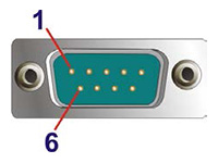
1 TXD422- TXD485- 2 TXD422+ TXD485- 3 RXD422+ 4 RXD422-
BIOS Adjustments
- Press DEL key after turning on the player to enter the BIOS menu.
- Enter Advanced -> F81803 Super IO Configuration -> Serial Port 1 Configuration.
- Locate Transfer Mode RS232 settings and select RS-232 (default), RS-422 or RS-485 as the Serial Port 1 signaling mode.
Video In

In the left column, you can see all UVC (USB Video Class) video input devices connecting to the player. Select a device and adjust related parameters.
| Pixel Format | Select a resolution and frame rate. |
|---|---|
| Brightness | To adjust the brightness from 0 to 100 by every 5 degrees. |
| Contrast | To adjust the contrast from 0 to 100 by every 5 degrees. |
| Saturation | To adjust the saturation from 0 to 100 by every 5 degrees. |
| Hue | To adjust hue from 0 to 100 by every 1 degree. |
| Gamma | To adjust gamma from 0 to 100 by every 1 degree. |
| Sharpness | To adjust the sharpness from 0 to 100 by every 1 degree. |
| TV Standard (for analog capture card only) | Set video input type. The input type can be NTSC, PAL and SECAM. |
| Over scan (for analog capture card only) | To adjust the over scan from 0 to 100 by every 5 degrees. You can use this option to adjust the image size. For example, 5 -> 105% and 10->110% |
For more informaiton about USB UVC capture card, please refer to the white paper.
Back to TopSound

In the left column, you can check the model of the embedded sound card and the output device you are using now.
In the right column, you can adjust the system volume immediately. Click the minus button, ![]() , to lower the sound or click the plus button,
, to lower the sound or click the plus button, ![]() , to increase the sound volume immediately. The sound will be louder when the number is bigger.
, to increase the sound volume immediately. The sound will be louder when the number is bigger.
Please click Edit in the right column, if you want to adjust the system volume based on a pre-set schedule. Then you can configure settings in SCHEDULE > Volume page.
Select Audio Output
User can choose either digital (HDMI/DP) audio or analog audio (phone jack). If you connect more than one screens to an SMP player, all digital audio will have the same outputs simultaneously in Clone/Extend mode. In Distinct mode, the sounds of each individual screen (digital output only) can be split for certain models. Please refer to the following comparison table:
| Model | Digital Audio Connection Type | Distinct Mode | Clone/Extended Mode |
|---|---|---|---|
| SMP-2100 | HDMI x 2 |
|
Mixed sound to all HDMI audio |
| SMP-2200 | HDMI x 2 | Separate sound | Mixed sound to all HDMI |
| SMP-2210 | HDMI x 2 | Separate sound | Mixed sound to all HDMI |
| SMP-2300 | HDMI x 3 | Separate sound (HDMI 3 supports video output only, no audio output) |
Mixed sound to all HDMI (HDMI 3 supports video output only, no audio output) |
| SMP-2310 | HDMI x 3 | Separate sound (HDMI 3 supports video output only, no audio output) |
Mixed sound to all HDMI (HDMI 3 supports video output only, no audio output) |
| SMP-6000 | HDMI x 1 | N/A | N/A |
| SMP-8000 | DP x 4 | Mixed sound to all DP audio | Mixed sound to all DP audio |
| SMP-8000QD | DP x 4 | Mixed sound to all DP audio | Mixed sound to all DP audio |
| SMP-8100 | HDMI x 4 | Depend on Playback settings* | Mixed sound to all HDMI audio |
* Audio output corresponds to the Playback settings. For example:
HDMI1 and HDMI2 together form Playback1, which corresponds to a single output on these two screens.
HDMI3 and HDMI4 together form Playback2, which corresponds to a single output on these two screens.
Note |
|---|
|
Touch Screen

After connecting a touch screen to the SMP player, you can check the model of the screen in the left column and select a video output mapping to the touch screen in the right column.
Calibration is not necessary for most touch panels that CAYIN tested, so you can use Auto-detect for most cases. However, you still can enter proper parameters for the touch screen in the right column.
| Auto-detect | Automatically read parameters from the Touch controller. This is the default setting. |
|---|---|
| Configure manually | Enter suitable X and Y axis parameters here. You can consult the touch screen manufacturer or press Crtl+F8 to try it by yourself. |
If you need to calibrate your touch screen which is mapping to HDMI2, we strongly suggest you change the display mode to Single mode before the calibration. Then, switch back to the display mode you were using (e.g. distinct or extended mode) after you calibrate the touch screen successfully.
Note |
|---|
|
USB

In the left column, all USB devices connecting to the player will be listed here. In the right column, you can change USB service settings.
You can select Disable to disable USB service completely to prevent possible access to SMP player through the USB port when not in use. Select Enable to resume USB service.
Note |
|---|
Please be aware that you won’t be able to connect a keyboard or mouse directly to the SMP player to do on-site maintenance tasks if you disable USB service. Instead, you need to connect to SMP’s Web Manager via network. |